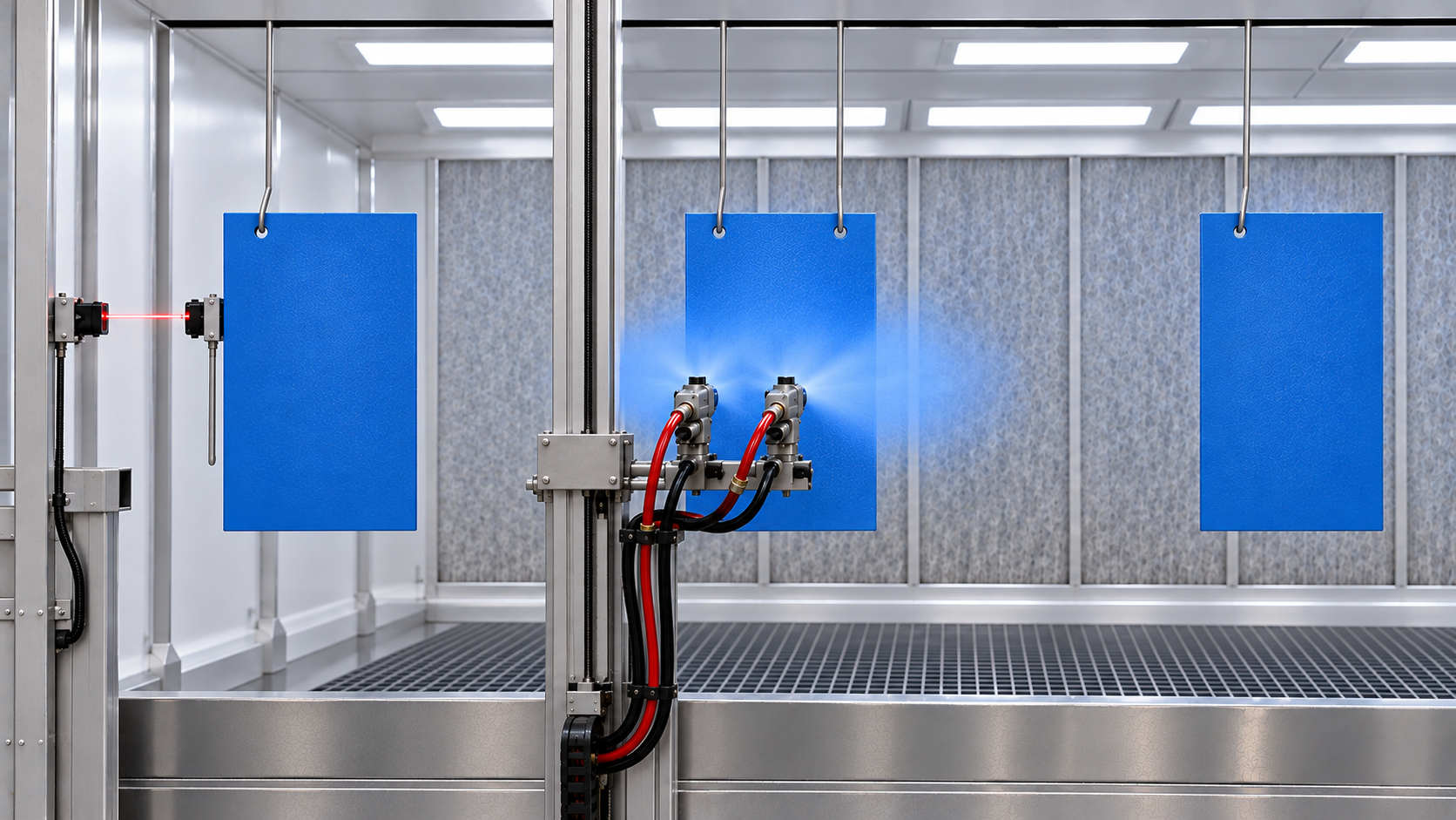
 Good Automatic Spraying Begins Before the Gun Opens
An automatic spray gun does not know when a part arrives. It does not know how fast the conveyor is moving, where the leading edge begins, or when the trailing edge has passed.
The gun simply responds to a control signal.
Producing consistent automatic coverage requires a complete control chain:
- A sensor detects the part.
- The control system tracks the part’s position.
- The gun receives an ON signal at the correct time.
- The gun opens and coating begins flowing.
- The spray reaches the leading edge of the part.
- The gun receives an OFF signal.
- Coating stops after the trailing edge passes.
If any part of that sequence is wrong, the finish can show light leading edges, heavy trailing edges, excessive overspray, uncoated areas, or coating on hooks and conveyor equipment.
Automatic spraying is not just about aiming the gun. It is about seeing the part, tracking its movement, and triggering the gun at exactly the right time.
The Basic Automatic-Spray Control System
A typical automatic liquid-finishing system may include:
- One or more part-detection sensors
- A conveyor encoder or speed signal
- A programmable logic controller, commonly called a PLC
- A timing controller or gun-triggering module
- Solenoid-operated pilot-air valves
- One or more automatic spray guns
- Booth and ventilation interlocks
- Part recipes or spray programs
- Operator controls and fault indicators
Simple systems may use a photoelectric sensor and adjustable time-delay relay. More advanced systems use encoders, multiple sensors, height detection, part identification, gun zoning, and stored recipes.
Part Detection Starts the Sequence
The part-detection sensor tells the control system that a workpiece has entered the spray process.
Common sensing technologies include:
- Through-beam photoelectric sensors
- Retroreflective photoelectric sensors
- Diffuse-reflective photoelectric sensors
- Laser sensors
- Background-suppression sensors
- Inductive proximity sensors
- Ultrasonic sensors
- Light curtains or sensor arrays
- Machine-vision systems
- Part-identification switches or barcode systems
The correct sensor depends on the parts, conveyor, booth environment, required detection distance, and control-system design.
Choosing the Right Sensor
A sensor that works perfectly on one product may fail on another.
Consider:
- Part size and shape
- Part color
- Surface reflectivity
- Openings or gaps in the part
- Minimum distance between parts
- Conveyor speed
- Sensor response time
- Booth lighting
- Overspray contamination
- Temperature and humidity
- Mounting distance
- Required environmental rating
Highly reflective, dark, curved, clear, perforated, or irregularly shaped parts can be difficult to detect reliably. The sensor must be tested with the actual range of production parts—not only with a convenient sample panel.
Through-Beam Detection
A through-beam photoelectric system uses a light emitter on one side of the conveyor and a receiver on the other. A part is detected when it interrupts the beam.
Through-beam systems are often dependable because the sensor does not rely on light reflecting from the part’s surface. However, the emitter and receiver must remain properly aligned.
Openings in a part may repeatedly break and restore the beam. Without signal conditioning, the control system may interpret one perforated part as several separate parts.
Retroreflective and Diffuse Sensors
A retroreflective sensor sends light toward a reflector and detects a part when the return signal is interrupted.
A diffuse-reflective sensor detects light reflected directly from the part.
These designs can simplify installation because the primary wiring may remain on one side of the conveyor. However, part color, angle, shape, gloss, and reflectivity can influence performance.
A shiny surface may reflect light away from the receiver. A dark surface may return too little light. A curved surface may create inconsistent signals as it moves.
Polarized retroreflective sensors, background-suppression sensors, or another sensing method may be needed for difficult parts.
Detect the Part—not the Hanger
The sensor should distinguish between the part and the conveyor’s hooks, racks, fixtures, carriers, and chain components.
Poor sensor placement can cause guns to spray every passing hanger. That wastes coating, contaminates fixtures, increases stripping costs, and may interfere with grounding.
Position and configure the sensor so that:
- The smallest approved part is detected.
- The largest part does not exceed the sensing range.
- Empty hooks do not trigger the guns.
- Openings do not create false trailing edges.
- Adjacent parts remain distinguishable when required.
- Overspray accumulation can be inspected and cleaned.
The Pickoff Distance
The sensor is normally installed upstream from the automatic spray guns. The distance from the sensor’s detection point to the gun’s spray position is often called the pickoff distance.
The controller uses this distance to determine when the detected part will reach the spray zone.
Measure the distance along the actual conveyor path. Do not rely on a straight-line measurement if the conveyor changes direction or elevation between the sensor and gun.
Use a consistent reference point, such as:
- The sensor beam
- The leading edge of the part
- The gun’s spray centerline
- The point where the pattern reaches the workpiece
A small error in the pickoff distance can become a large timing error at higher conveyor speeds.
Time-Based Triggering
A simple system can calculate the delay between part detection and gun triggering from the conveyor speed and sensor-to-gun distance.
Travel Time in Seconds = Distance in Feet ÷ Conveyor Speed in Feet per Minute × 60
For example, if the sensor is 10 feet upstream from the spray position and the conveyor travels at 20 feet per minute:
10 Feet ÷ 20 FPM × 60 = 30 Seconds
The calculated 30 seconds is a starting point. The final setting must also account for control response, gun opening time, fluid response, spray distance, and the desired coverage margin.
Time-based triggering works best when conveyor speed remains constant. If the conveyor speeds up or slows down, the part will reach the gun earlier or later than the fixed timer predicts.
Encoder-Based Tracking
An encoder measures conveyor movement and sends pulses to the control system. Instead of assuming that the conveyor maintains one speed, the controller tracks how far the conveyor has actually moved.
The controller may store:
- Sensor-to-gun distance in encoder counts
- Part length in encoder counts
- Gun ON position
- Gun OFF position
- Leading-edge adjustment
- Trailing-edge adjustment
Encoder-based tracking is normally more dependable when conveyor speed varies. If the conveyor slows, the encoder pulses slow. If the conveyor stops, the pulse count stops.
The encoder must be mechanically connected so that it accurately represents conveyor travel. A slipping wheel, loose chain, worn sprocket, incorrect scaling factor, or failed coupling can create timing errors even when the controls appear normal.
Gun Response Is Not Instantaneous
The controller may send an ON signal immediately, but the coating does not instantly appear at the workpiece.
The total response includes:
- Sensor response time
- PLC scan time
- Output-module response
- Solenoid-valve response
- Pilot-air travel through the tubing
- Gun actuator movement
- Needle opening
- Fluid-system response
- Coating travel from the gun to the part
The same principle applies when the gun closes. A small amount of coating may continue after the OFF signal because of valve response, hose expansion, fluid pressure, and material remaining at the nozzle.
The gun’s actual spray response must be observed and included in the final timing adjustment.
Lead and Lag Adjustments
The gun may need to begin spraying slightly before the leading edge reaches the center of the pattern. It may also need to remain on until the trailing edge moves beyond the spray zone.
These adjustments may be called:
- Lead and lag
- Advance and delay
- ON and OFF offset
- Trigger and extend
- Pickoff, delay, and extension
The terminology varies among control manufacturers, so the operator must understand what each setting actually changes.
Leading-Edge Adjustment
If the gun starts too late, the leading edge may receive too little coating. If it starts too early, coating may be sprayed into the booth or onto an empty hanger before the part arrives.
Trailing-Edge Adjustment
If the gun stops too soon, the trailing edge may be light or uncoated. If it stops too late, coating may build on hooks, fixtures, conveyor components, or the booth.
The correct setting provides full coverage while minimizing off-part spray.
Part Length and Signal Conditioning
The control system must know when the leading edge enters the sensor and when the trailing edge leaves it.
Parts with holes, slots, spokes, or separated sections may cause the sensor signal to switch repeatedly.
Signal-conditioning functions may include:
- ON delay
- OFF delay
- Debounce timing
- Gap suppression
- Minimum-part-length filtering
- Maximum-part-length alarms
- Signal extension
Gap suppression allows a short opening in the part to be ignored so that the controller continues treating the object as one part.
Minimum-length filtering may prevent small hooks or conveyor hardware from being identified as parts.
These settings must be tested carefully. Excessive signal extension can cause two closely spaced parts to be treated as one long part.
Multiple Guns and Spray Zones
A finishing system may have several automatic guns positioned at different heights or distances along the conveyor.
Each gun may require its own:
- Pickoff distance
- ON adjustment
- OFF adjustment
- Part-height zone
- Fluid and atomizing-air setting
- Pattern width
- Reciprocator position
Do not assume that one trigger setting will work for every gun. A gun farther downstream must be tracked separately. Guns aimed at different areas may also need different leading- and trailing-edge margins.
Height and Width Detection
A single photoeye can detect that a part is present, but it may not identify the part’s height or shape.
Vertical sensor arrays or light curtains can divide the spray zone into height sections. The control system then activates only the guns needed to coat the detected portion of the part.
This can:
- Reduce off-part spraying
- Save coating
- Reduce booth loading
- Keep unused guns off
- Adapt automatically to different part heights
More advanced systems may combine height detection with part recipes, width sensors, reciprocator control, or machine vision.
Conveyor Interlocks Matter
Automatic guns should not continue spraying when the conveyor stops unexpectedly.
The control system should monitor actual conveyor movement—not merely whether the conveyor start command is active.
An encoder, motion switch, or verified speed signal can help detect:
- Conveyor stoppage
- Encoder failure
- Drive-chain failure
- Unexpected speed changes
The required interlocks should also prevent automatic spraying when booth ventilation is not operating correctly.
The control system should be designed so that a failed sensor, lost speed signal, stopped conveyor, or failed booth interlock causes a safe response.
Set Up the System in the Correct Order
Do not begin by randomly adjusting timers.
Use a controlled setup process:
- Verify the conveyor’s actual speed.
- Confirm encoder operation and scaling, if used.
- Align and test the part-detection sensor.
- Confirm that empty hooks do not trigger the system.
- Measure the sensor-to-gun pickoff distance.
- Confirm the gun’s actual spray centerline.
- Enter the starting timing or encoder-count values.
- Verify the correct gun-to-sensor assignments.
- Test the control sequence without coating.
- Run a test part at normal production speed.
- Observe the leading and trailing edges.
- Adjust one setting at a time.
- Document the final approved settings.
Use Test Mode Before Spraying Coating
When available, use the controller’s test or simulation mode to verify:
- Sensor input
- Part tracking
- Gun-output assignment
- Solenoid operation
- ON and OFF sequence
- Conveyor-stop response
- Booth-exhaust interlock
The first test should confirm control logic without unnecessarily spraying coating.
After the dry test is successful, conduct a controlled spray test using an approved test panel or production part.
Diagnosing Timing Problems From the Part
Light Leading Edge
Possible causes include:
- Gun turns on too late
- Incorrect pickoff distance
- Slow solenoid or gun response
- Low pilot-air pressure
- Delayed fluid response
- Incorrect encoder scaling
Heavy Leading Edge
Possible causes include:
- Gun turns on too early
- Excessive leading-edge extension
- Part slows before reaching the gun
- Gun initially delivers an unstable burst
Light Trailing Edge
Possible causes include:
- Gun turns off too early
- Trailing-edge extension is too short
- Part openings create a false trailing edge
- Sensor signal drops out
Coating Beyond the Trailing Edge
Possible causes include:
- Gun turns off too late
- Excessive signal extension
- Slow gun closing
- Fluid pressure or hose expansion delays cutoff
- Two parts are being interpreted as one
Timing Changes With Conveyor Speed
Possible causes include:
- Fixed-time control is being used on a variable-speed conveyor
- Encoder signal is missing or unstable
- Encoder scaling is incorrect
- The encoder wheel or drive is slipping
- The PLC is using commanded speed instead of actual movement
Maintain the Detection System
A timing program cannot compensate indefinitely for dirty or misaligned equipment.
Regularly inspect:
- Sensor lenses
- Reflectors
- Emitter and receiver alignment
- Mounting brackets
- Electrical cables and connectors
- Encoder wheels, chains, and couplings
- Solenoid valves
- Pilot-air tubing
- Gun needles, seals, and actuators
- PLC inputs and outputs
- Conveyor and booth interlocks
Clean sensors using methods approved by the manufacturer. Solvents, abrasive wiping, or sharp tools may damage the lens.
Document Settings by Part
Different products may require different spray timing.
An approved part recipe may include:
- Part number or family
- Conveyor speed
- Sensor assignment
- Gun assignment
- Pickoff value
- Leading-edge adjustment
- Trailing-edge adjustment
- Gap-suppression value
- Gun fluid pressure
- Atomizing-air pressure
- Pattern-air setting
- Gun-to-part distance
- Reciprocator settings
- Approved coating result
Protect approved recipes from unauthorized changes. Record revisions so that a successful setup can be restored after maintenance or troubleshooting.
A Practical Timing and Detection Checklist
Before automatic production begins, confirm:
- The sensor detects every approved part.
- The sensor ignores empty hooks and fixtures.
- The sensor remains reliable across different colors and finishes.
- Openings in the part do not create false signals.
- The pickoff distance has been measured correctly.
- The actual conveyor speed has been verified.
- The encoder is operating and properly scaled.
- Each gun is assigned to the correct sensor or zone.
- Gun ON timing covers the leading edge.
- Gun OFF timing covers the trailing edge.
- Off-part spray is minimized.
- The guns stop when conveyor motion stops.
- The guns cannot operate without required booth ventilation.
- The approved settings have been documented.
The Bottom Line
Automatic guns do not improve consistency simply because they are automatic.
Consistency comes from reliable part detection, accurate conveyor tracking, correct pickoff distance, predictable gun response, and carefully verified ON and OFF settings.
The sensor must see the correct part. The controller must know where that part is. The gun must open early enough to cover the leading edge and close soon enough to avoid spraying empty space.
See the part. Track the part. Spray the part—and nothing else.
This article provides general educational information. Automatic spray systems must be installed, programmed, operated, and maintained according to the equipment manufacturer’s instructions, applicable safety requirements, and the facility’s approved procedures.
Technical Resources
© 2026 Azimuth Spray Systems, LLC. All rights reserved.