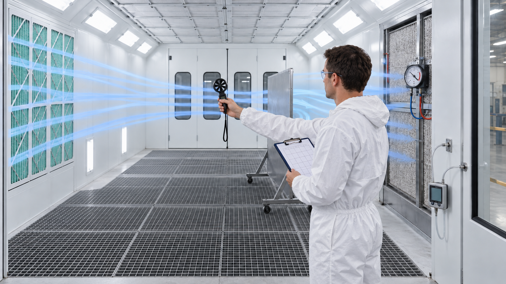
 The Booth Fan Is Running—but Is the Air Moving Correctly?
A spray-booth exhaust fan can be noisy, booth lights can be bright, and air may appear to be moving—but none of those observations proves that the booth is ventilating correctly.
The only dependable way to evaluate spray-booth airflow and pressure is to measure them.
Airflow measurements help determine whether the booth is moving enough air to carry overspray and solvent-laden air away from the painter. Pressure measurements help determine whether the booth is balanced and whether its filters are becoming loaded.
These measurements affect:
- Employee exposure
- Overspray control
- Finish quality
- Booth cleanliness
- Filter service life
- Fan performance
- Shop contamination
- Fire and explosion prevention
- Regulatory compliance
If airflow is too low, overspray and vapors may remain in the booth. If airflow is excessive or poorly distributed, it can distort the spray pattern, increase coating waste, and create turbulence around the workpiece.
The goal is not simply more air. The goal is the correct amount of air moving in the correct direction.
Three Measurements That Should Not Be Confused
Spray-booth airflow and pressure are related, but they are not the same measurement.
A complete booth evaluation may include:
- Air velocity: How fast the air is moving through a particular area
- Air volume: How much air the system moves over time
- Pressure differential: The pressure difference between two locations
A pressure gauge does not directly measure air velocity. An anemometer reading does not directly show filter resistance. Each instrument answers a different question.
Air Velocity: How Fast Is the Air Moving?
Air velocity is commonly measured in feet per minute, abbreviated FPM.
An anemometer is the instrument most often used to measure booth air velocity. Common types include:
- Vane anemometers
- Hot-wire anemometers
- Thermal anemometers
The correct instrument depends on the expected velocity, measurement location, environmental conditions, and required accuracy.
Air velocity is rarely identical at every point in a booth. One reading in the center does not represent the entire airflow pattern.
Measurements should be taken across a planned grid so that high-flow areas, low-flow areas, dead zones, and turbulence can be identified.
Air Volume: How Much Air Is the Booth Moving?
Air volume is commonly expressed in cubic feet per minute, abbreviated CFM.
If the average air velocity and the cross-sectional area are known, approximate air volume can be calculated:
CFM = Average Air Velocity in FPM × Area in Square Feet
For example, if the average velocity across an opening is 100 feet per minute and the measured opening is 80 square feet:
100 FPM × 80 Square Feet = 8,000 CFM
This calculation is only as reliable as the measurements used. An incorrect area, too few velocity readings, or readings taken in the wrong plane can produce a misleading result.
Pressure Differential: What Is Resisting or Directing the Air?
Pressure differential is the difference in air pressure between two locations. Spray-booth pressure is commonly measured in inches of water column, often written as inches w.c.
Pressure measurements may be used to evaluate:
- Resistance across intake filters
- Resistance across exhaust filters
- Pressure inside the booth compared with the surrounding room
- Pressure within an intake or exhaust plenum
- Fan and duct-system performance
A manometer, differential-pressure gauge, or electronic pressure instrument may be used, depending on the booth and required accuracy.
Filter Pressure Is Not Booth Pressure
These two measurements are often confused.
Filter Differential Pressure
>
TM
Filter differential pressure measures the pressure immediately upstream and downstream of a filter bank. It indicates the resistance created by the filters.
As filters collect dust or overspray, their resistance normally increases. The pressure reading can therefore help determine when the filters should be replaced.
Booth-to-Room Pressure
Booth pressure compares the air pressure inside the booth with the pressure in the surrounding room or building.
This measurement indicates whether the booth is operating:
- Positive to the surrounding area
- Negative to the surrounding area
- Approximately neutral or balanced
The correct pressure relationship depends on the booth design and application.
A booth intended to operate slightly positive may help prevent shop dust from entering the finishing area. A booth intended to operate slightly negative may help contain overspray and vapors.
Too much positive pressure can push contaminated air into the shop. Too much negative pressure can pull dirt into the booth, make doors difficult to open, and disrupt the designed airflow.
Start With the Booth’s Design Requirements
There is no single airflow or pressure number that applies to every spray booth.
Before taking measurements, identify:
- The booth manufacturer and model
- The booth’s airflow design
- The original design airflow
- The required average air velocity
- The intended booth-pressure relationship
- The approved intake and exhaust filters
- The clean-filter and final-filter pressure limits
- Applicable OSHA requirements
- Applicable fire-code requirements
- Environmental-permit conditions
- Requirements for the coating and application process
Do not assume that a number used for a crossdraft booth also applies to a downdraft booth. The direction of airflow, measurement plane, booth opening, workpiece position, and operating mode all matter.
Crossdraft-Booth Measurement
In a crossdraft booth, air generally enters through filters at one end, moves horizontally through the spraying area, and exits through paint-arrestor filters at the opposite end.
The measurement procedure should follow the booth manufacturer’s instructions and applicable regulations. Depending on the booth design, measurements may be taken across the booth opening, intake face, or another specified plane.
A typical velocity survey includes:
- Divide the measurement plane into an evenly spaced grid.
- Take a velocity reading at the center of each grid section.
- Keep the instrument facing the airflow correctly.
- Allow each reading to stabilize.
- Record every reading—not only the highest readings.
- Add the readings and divide by the number of readings.
- Compare the average and individual readings with the required criteria.
The average may appear acceptable even when one section has very low airflow. Review the pattern of readings as well as the calculated average.
2>
Downdraft-Booth Measurement
_CURRENT
In a downdraft booth, air enters through ceiling filters, moves downward around the object, and exits through floor-level filters, pits, or lower exhaust chambers.
Velocity measurements are normally taken across a horizontal plane or at locations specified by the booth manufacturer, testing standard, or authority having jurisdiction.
A downdraft booth may show acceptable total airflow but still have uneven distribution because of:
- Loaded ceiling filters
- Missing or incorrectly installed filters
- Blocked floor grating
- Uneven exhaust-filter loading
- Parts or fixtures obstructing airflow
- Incorrect damper settings
- Makeup-air problems
Measure enough locations to identify whether the air is distributed evenly across the useful booth area.
Side-Draft and Semi-Downdraft Booths
Side-draft and semi-downdraft booths combine horizontal, diagonal, or downward airflow patterns.
A simple face-velocity test may not provide enough information to evaluate these booths. Follow the manufacturer’s designated measurement planes and testing procedure.
When the airflow path is complex, a qualified ventilation professional may be needed to evaluate:
- Air distribution
- Capture effectiveness
- Fan performance
- Plenum balance
- Duct velocity
- Makeup-air volume
Prepare the Booth Before Testing
Testing conditions must be documented. A booth measured under one set of conditions may perform differently under another.
Before testing:
- Stop spray application.
- Remove unnecessary personnel from the booth.
- Confirm that the booth is safe to enter.
- Inspect intake and exhaust filters.
- Confirm that all filters are installed correctly.
- Inspect fan belts, guards, motors, and dampers.
- Check floor grates and air passages for blockage.
- Place doors and access panels in their normal operating positions.
- Operate exhaust and makeup-air systems in the mode being evaluated.
- Allow the system to stabilize.
- Confirm that the measuring instruments are appropriate and calibrated.
Document whether the readings are being taken with clean filters, partially loaded filters, or filters approaching their change point.
Use a Measurement Grid
A measurement grid provides a more representative picture than one or two spot readings.
The grid should cover the required measurement plane. The number and spacing of test points should follow the manufacturer’s procedure, applicable standard, or test protocol.
Avoid taking all readings:
- Only in the center of the booth
- Directly against a filter face unless required
- Too close to walls or structural obstructions
- Where the technician’s body blocks the airflow
- Where doors, hoses, or equipment disturb the reading
Hold the instrument consistently at every location. Changing its direction or angle can affect the results.
Measure Filter Differential Pressure Correctly
A filter-pressure gauge must be connected to the correct pressure locations.
One sensing point should represent pressure upstream of the filter bank, and the other should represent pressure downstream. The ports and tubing must be open, undamaged, and connected to the proper sides of the gauge.
Before relying on the reading:
- Inspect the tubing for cracks, kinks, paint, or blockage.
- Confirm that the pressure ports are clear.
- Check the instrument’s zero position according to its instructions.
- Confirm that the gauge range is appropriate.
- Verify that the instrument is mounted in the correct position.
- Compare the reading with the clean-filter baseline.
A gauge stuck at zero does not necessarily mean the filters are clean. The tubing may be disconnected or blocked, or the gauge may be defective.
Establish a Clean-Filter Baseline
After installing the correct new filters, operate the booth under documented normal conditions and record:
- Average air velocity
- Individual grid readings
- Calculated airflow volume
- Intake-filter pressure drop
- Exhaust-filter pressure drop
- Booth-to-room pressure
- Fan and makeup-air settings
- Door and damper positions
This information becomes the booth’s clean-filter performance baseline.
Future readings can be compared with the baseline to identify gradual deterioration, sudden system changes, or incorrect filter installation.
Measure Booth-to-Room Pressure
Booth pressure is measured with one pressure reference inside the booth and the other in the surrounding room or designated reference area.
Because booth-pressure differences may be very small, the instrument must have enough sensitivity to measure them accurately.
The test should be conducted with:
- Booth doors in their normal operating positions
- Exhaust fan operating
- Makeup-air unit operating as intended
- Shop doors and major air-moving equipment in documented positions
- The heating or curing system in the mode being evaluated
Nearby exhaust fans, open loading doors, building pressure, wind, and HVAC operation can all influence the result.
Smoke Testing Shows Direction—not Quantity
A smoke tube or another approved visualization method can help identify:
- Airflow direction
- Turbulence
- Dead zones
- Air leakage
- Booth-to-room containment
- Flow around large workpieces
Smoke visualization is useful, but it does not replace an anemometer, pressure gauge, or formal airflow test. It shows where the air is going—not how many feet per minute or cubic feet per minute are moving.
Only use visualization products and procedures that are safe for the booth environment. Never introduce an ignition source into an area that may contain flammable vapors.
Air Changes per Hour Can Be Misleading
Air changes per hour describe how many times the calculated room volume would be replaced in one hour.
Air Changes per Hour = CFM × 60 ÷ Booth Volume
This calculation can be useful for general ventilation analysis, but it does not prove that overspray is being captured or that air is moving correctly through the painter’s breathing zone.
A booth may have a high calculated air-change rate and still contain dead zones, turbulence, or an incorrect airflow direction.
Do not use air changes per hour as a substitute for the airflow criteria that apply to the specific spray operation.
Interpreting the Results
A test result should not be evaluated in isolation.
Consider:
- The booth manufacturer’s requirements
- Applicable OSHA ventilation requirements
- Fire-code requirements
- Environmental-permit conditions
- The coating’s hazards
- The spray method and application rate
- The position and size of the workpiece
- Filter condition
- Makeup-air and exhaust-fan performance
If readings are below the required level, do not immediately increase fan speed without identifying the cause. The problem may be loaded filters, slipping belts, closed dampers, blocked ductwork, incorrect fan rotation, inadequate makeup air, or a mechanical defect.
Common Measurement Mistakes
Avoid these common errors:
- Taking only one velocity reading
- Measuring without a planned grid
- Using an instrument outside its proper range
- Using an instrument that has not been calibrated
- Standing where the body blocks or redirects airflow
- Comparing crossdraft and downdraft measurements as though they are identical
- Testing with doors in the wrong position
- Ignoring the makeup-air system
- Confusing filter pressure drop with booth pressure
- Assuming visible smoke movement proves adequate velocity
- Failing to record filter condition
- Using a generic target instead of the booth’s required value
Build a Booth-Performance Record
Record each inspection and test so that changes can be identified over time.
A useful record includes:
- Date and time
- Name of the person conducting the test
- Instrument type and identification
- Calibration status
- Booth operating mode
- Door and damper positions
- Filter type and condition
- Every velocity-grid reading
- Calculated average velocity
- Calculated airflow volume
- Filter differential-pressure readings
- Booth-to-room pressure
- Workpiece or fixture configuration
- Observed airflow problems
- Corrective actions taken
A history of readings can show whether the booth is gradually losing performance or whether a sudden change occurred after maintenance, filter replacement, equipment installation, or building modification.
When to Bring In a Professional
A qualified booth technician, ventilation engineer, industrial hygienist, or testing professional should be consulted when:
- The booth cannot maintain its required airflow.
- Measurements vary widely across the booth.
- Overspray remains suspended in the spraying area.
- Contaminated air escapes into the shop.
- The booth has been modified from its original design.
- The fan, motor, ductwork, or makeup-air system has changed.
- Employee exposure levels are uncertain.
- Airflow must be documented for a permit or inspection.
- The correct measurement plane or acceptance criteria are unclear.
A Practical Airflow and Pressure Checklist
Before approving the booth for spraying, confirm:
- The airflow requirements have been identified.
- The booth has been inspected for blockages and damage.
- All filters are correctly installed.
- The exhaust and makeup-air systems are operating.
- Air velocity has been measured across the required grid.
- Average velocity has been calculated correctly.
- Low-flow areas have been investigated.
- Filter differential pressure is within the approved range.
- Booth-to-room pressure matches the design.
- Airflow direction is correct.
- The booth contains overspray as intended.
- All results and corrective actions have been documented.
The Bottom Line
A fan that turns is not proof of proper ventilation. A pressure gauge that has not been checked is only decoration. A single velocity reading does not describe an entire spray booth.
Measure air velocity across the correct plane. Calculate airflow using a representative average. Monitor pressure across the filters. Check the booth’s pressure relationship with the surrounding room. Record the results and compare them with the booth’s actual requirements.
If airflow protects the painter and controls the finish, it is too important to guess.
This article provides general educational information. It is not a substitute for the spray-booth manufacturer’s instructions, a workplace-specific hazard assessment, professional ventilation testing, environmental-permit requirements, or applicable federal, state, and local regulations.
Authoritative Resources
© 2026 Azimuth Spray Systems, LLC. All rights reserved.