|
|
|
The Difference Between WFT and DFT Last Updated: 09/15/2026 |
||||||||||||||||||||||||
|
 The Difference Between WFT and DFT
| Comparison | WFT | DFT |
|---|---|---|
| Full name | Wet-film thickness | Dry-film thickness |
| When measured | Immediately after application | After sufficient drying or curing |
| What it includes | Solids plus water, solvent, and other volatile material | The film remaining after volatile material leaves |
| Typical instrument | Notched wet-film gauge | Magnetic, eddy-current, ultrasonic, or destructive gauge |
| Primary purpose | Application process control | Finished-film verification |
| Can application be adjusted? | Often, while the coating is still wet | Usually requires recoating, removal, or repair |
| Typical role | Helps predict final thickness | Confirms the actual final thickness |
Why Is WFT Usually Greater Than DFT?
A liquid coating contains film-forming solids and volatile ingredients. The volatile portion may include water, solvent, or other material that leaves during drying or curing.
As volatile material leaves, the coating becomes thinner. The percentage of the original wet volume theoretically remaining in the dry film is identified as the coating’s solids by volume.
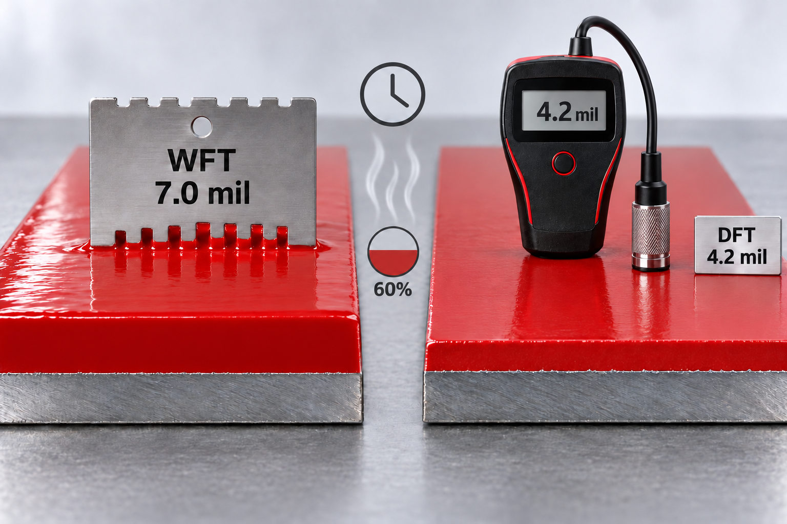
For example, a coating containing 60% solids by volume retains approximately 60% of its applied wet volume as dry film. The remaining approximately 40% represents the volatile portion.
Recognized methods for determining volume nonvolatile matter include ASTM D2697—Volume Nonvolatile Matter in Clear or Pigmented Coatings .
The Basic WFT and DFT Relationship
For an unreduced coating, the basic relationship is:
DFT = WFT × Volume Solids as a Decimal
To calculate the required WFT:
WFT = Required DFT ÷ Volume Solids as a Decimal
Use solids by volume for these calculations. Do not substitute solids by weight.
Example: Converting WFT to DFT
A coating containing 60% solids by volume is applied at 7 mils WFT.
7 mils WFT × 0.60 = 4.2 mils DFT
The theoretical dry-film thickness is approximately 4.2 mils.
Example: Calculating the Required WFT
A project requires 5 mils DFT. The coating contains 65% solids by volume.
5 mils DFT ÷ 0.65 = 7.69 mils WFT
The theoretical wet-film target is approximately 7.7 mils.
Because most notched gauges measure between two tooth values, the applicator may need to select a practical target range that brackets the calculated value.
Metric Calculations Work the Same Way
The formulas do not change when thickness is measured in microns.
Suppose a project requires 125 microns DFT and the coating contains 70% solids by volume:
125 microns ÷ 0.70 = 179 microns WFT
The theoretical wet-film target is approximately 179 microns.
How Thinning Changes the WFT-to-DFT Relationship
Thinner or reducer normally adds liquid volume without adding film-forming solids. The mixed coating therefore has a lower effective percentage of solids by volume.
If the WFT remains unchanged after thinning, the resulting DFT will generally be lower.
When thinner is added as a percentage of the original coating volume, effective volume solids may be estimated using:
Effective Volume Solids = Original Volume Solids ÷ (1 + Thinner Fraction)
Example: Adding 10% Thinner
A coating contains 60% solids by volume. Ten percent thinner is added based on the original coating volume.
60% ÷ 1.10 = 54.5% Effective Volume Solids
If the project requires 4 mils DFT:
4 mils ÷ 0.545 = 7.34 mils WFT
Without thinner, the same coating would theoretically require:
4 mils ÷ 0.60 = 6.67 mils WFT
Adding 10% thinner increased the theoretical WFT requirement from approximately 6.7 mils to approximately 7.3 mils.
Always follow the manufacturer’s approved reduction instructions. The expression “10% reduction” should be confirmed because mixing conventions can differ.
WFT Is a Process-Control Measurement
WFT testing is performed during application. Its primary purpose is to determine whether approximately the correct amount of wet coating is being deposited.
If WFT is too low, possible application adjustments may include:
- Reducing applicator travel speed.
- Improving spray-pattern overlap.
- Adjusting fluid delivery within approved limits.
- Correcting excessive spray-gun distance.
- Checking atomizing or airless pressure.
- Confirming that the coating was mixed and reduced correctly.
If WFT is too high, the applicator may need to:
- Increase travel speed.
- Reduce excessive overlap.
- Adjust fluid delivery.
- Evaluate coating viscosity.
- Check for excessive buildup around corners and welds.
- Review the number of spray passes.
All adjustments must remain within the coating manufacturer’s instructions and the approved application procedure.
DFT Is a Finished-Film Measurement
DFT is measured after the coating has dried or cured sufficiently. Its purpose is to determine the actual thickness remaining on the substrate.
DFT testing helps answer:
- Did the coating reach the specified minimum thickness?
- Did any areas exceed the specified maximum?
- Is film build reasonably consistent?
- Does the completed coating comply with the project requirements?
A procedure frequently specified for determining conformance on coated metal structures is SSPC-PA 2—Procedure for Determining Conformance to Dry Coating Thickness Requirements .
A single gauge reading should not normally be treated as proof that an entire coated area passes or fails. Multiple readings must be collected, grouped, and evaluated according to the governing procedure.
Why Calculated DFT and Measured DFT May Differ
The WFT-to-DFT calculation is theoretical. The final measured thickness may differ for several reasons:
- The WFT gauge measures only a small location.
- The coating may flow or level after the WFT reading.
- Solvent or water may leave before the reading is taken.
- The substrate may be rough, profiled, porous, or absorbent.
- Coating thickness varies across the spray pattern.
- The amount of thinner may have been estimated incorrectly.
- The components may have been mixed at the wrong ratio.
- The volume-solids value may include a stated tolerance.
- The DFT gauge may require adjustment for the substrate or profile.
- The coating may not have completed its drying or curing process.
The calculation provides a target. Direct measurement determines what was actually applied.
Effect of Abrasive-Blast Profile
Abrasive-blasted steel contains peaks and valleys. Wet coating fills the valleys and covers the peaks.
A wet-film comb references the surface it contacts, while a magnetic DFT gauge responds to magnetic properties beneath the coating. Surface roughness can therefore affect both the application calculation and the final measurement.
The DFT gauge should be adjusted or corrected according to the specified procedure. An improvised subtraction should not be used unless it is permitted by the governing standard or specification.
When Should WFT Be Measured?
Measure WFT as soon as practical after application and before the coating begins to:
- Lose a significant amount of solvent or water.
- Develop a surface skin.
- Set or cure.
- Flow away from the test location.
- Absorb into a porous substrate.
Fast-drying coatings require particularly prompt measurement.
When Should DFT Be Measured?
Measure DFT after the coating has dried or cured enough to resist probe contact without indentation or damage.
Measuring too soon can:
- Indent the coating.
- Produce a falsely low result.
- Contaminate the probe.
- Damage the finish.
Follow the manufacturer’s required drying or curing conditions. Dry-to-touch does not necessarily mean ready for final DFT acceptance.
Can WFT Replace DFT Testing?
No—not when the specification requires final dry-film thickness.
WFT is used to predict and control film build during application. It cannot confirm the thickness remaining after drying or curing.
A correct WFT reading can still produce an unexpected DFT because of:
- Incorrect volume-solids information.
- Unrecorded thinner.
- Surface absorption.
- Coating flow.
- Measurement error.
- Application variation.
- Surface-profile effects.
Can DFT Testing Replace WFT Testing?
DFT testing can verify the completed film, but it cannot provide immediate application control.
If a DFT problem is discovered after curing, correction may require:
- Additional surface preparation.
- Cleaning or sanding.
- Applying another coat.
- Removing excessive material.
- Repairing incompatible or poorly cured areas.
- Repeating inspection.
WFT testing can identify the developing problem while corrective action may still be simple.
Common WFT and DFT Mistakes
Using Weight Solids
The WFT-to-DFT calculation requires solids by volume. Solids by weight should not be substituted.
Ignoring Thinner
Added thinner lowers effective volume solids and increases the required WFT for the same DFT.
Assuming One Reading Represents the Entire Surface
Both wet- and dry-film thickness vary across the work. Multiple representative measurements are required.
Reporting a WFT Range as an Exact Number
A notched gauge generally establishes that the wet film lies between the highest wetted tooth and the next higher unwetted tooth.
Measuring DFT on a Soft Film
The probe may compress the film and produce an inaccurate result.
Ignoring the Substrate
Magnetic, eddy-current, and ultrasonic DFT gauges are intended for different substrate and coating combinations.
Confusing One Coat With the Total System
A conventional DFT gauge generally measures the combined thickness of all compatible nonmagnetic or nonconductive layers between the probe and the metal substrate.
Assuming Thicker Is Always Better
Excessive film build can be as harmful as insufficient film build.
Practical WFT and DFT Workflow
- Review the project specification and product data sheet.
- Confirm the required DFT range.
- Locate the solids-by-volume value.
- Confirm whether thinning is permitted.
- Calculate the target WFT.
- Apply the coating using the approved procedure.
- Measure WFT promptly in multiple representative locations.
- Adjust application technique when readings are outside the target.
- Allow the coating to dry or cure sufficiently.
- Select and verify the correct DFT gauge.
- Adjust for the actual substrate and surface profile when required.
- Collect multiple DFT readings according to the specified procedure.
- Document the results.
- Correct and retest nonconforming areas.
What Should Be Documented?
A useful coating-thickness record may include:
- Project and coated-area identification
- Coating manufacturer and product
- Batch or lot number
- Mixing ratio
- Approved thinner and amount added
- Solids by volume
- Specified DFT range
- Calculated WFT target
- Actual WFT readings
- DFT gauge manufacturer and model
- Calibration and verification information
- DFT readings, spot measurements, and area results
- Measurement locations
- Environmental conditions
- Application adjustments
- Corrective action and retest results
Primary Referenced Standards
- ASTM D4414—Measurement of Wet Film Thickness by Notch Gages
- ASTM D7091—Nondestructive Measurement of Dry Film Thickness
- ASTM D2697—Volume Nonvolatile Matter in Clear or Pigmented Coatings
- SSPC-PA 2—Procedure for Determining Conformance to Dry Coating Thickness Requirements
The Bottom Line
WFT and DFT are not competing measurements. They are two parts of the same coating-control process.
WFT tells the applicator what is being deposited while the work is underway. DFT tells the inspector what remains after the coating has dried or cured.
Volume solids connect the two:
WFT during application = Process control
DFT after curing = Finished-film verification
Calculate before spraying. Measure while applying. Verify after curing. That is how a specified film thickness becomes an actual coating system.
Technical Notice: This article provides general educational information and does not reproduce or replace the complete ASTM, AMPP/SSPC, coating-manufacturer, instrument-manufacturer, contract, safety, or project requirements. Standards and product instructions are revised periodically. Always obtain and follow the current documents specified for the coating project.
Copyright © 2026 Azimuth Spray Systems, LLC. All rights reserved. AirSprayTech.com—The Finishing Authority®. No portion of this article may be reproduced, distributed, republished, or transmitted without prior written permission.