|
|
|
How to Perform a Tape-Adhesion Test Last Updated: 09/15/2026 |
|||||||||||||||||||||||||||||||||
|
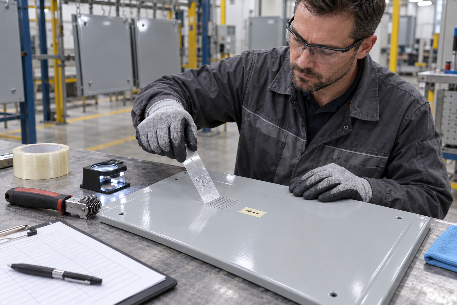 How to Perform a Tape-Adhesion Test
| Comparison | Method A | Method B |
|---|---|---|
| Cut pattern | X-shaped cut | Cross-cut lattice |
| Common application | Field testing and thicker films | Thin films and smooth test surfaces |
| Tool | Sharp cutting blade and straightedge | Single-blade guide or multi-tooth cutter |
| ASTM rating scale | 5A through 0A | 5B through 0B |
| Test effect | Destructive | Destructive |
Before Performing the Test
Determine the following before cutting the coating:
- Which test method is specified.
- The coating type and coating system.
- The total dry-film thickness.
- The substrate material.
- The required cure or conditioning time.
- The required cutter and cut spacing.
- The specified tape.
- The number and location of tests.
- The required acceptance rating.
- How the destructive test area will be repaired.
Do not perform a destructive adhesion test on a finished structure without authorization. The cuts expose the substrate and may create a future corrosion or coating-failure location if they are not repaired.
Tools and Materials
Depending on the selected procedure, the following may be required:
- A sharp cutting blade or approved cross-cut cutter
- A straightedge or cutting guide
- The pressure-sensitive tape required by the procedure
- A tape-smoothing tool or suitable eraser
- A soft brush
- A magnifier and adequate lighting
- A dry-film thickness gauge
- A ruler or spacing guide
- Cleaning materials approved for the coating
- A camera or inspection-recording device
- Materials for repairing the test area
- Appropriate gloves and eye protection
The Tape Matters
The pressure-sensitive tape is part of the test system. Do not assume that masking tape, packaging tape, duct tape, or whatever tape happens to be available will provide an equivalent result.
Tape characteristics can vary with:
- Manufacturer
- Product type
- Production lot
- Age
- Storage temperature
- Humidity
- Contamination
- Adhesive deterioration
Use the tape required by the current standard, project specification, or agreed test procedure. Store and condition it according to the applicable requirements.
The Cutter Matters Too
A dull, chipped, contaminated, or incorrect cutter can tear the coating instead of making a clean cut. This may produce misleading coating removal.
The cutter should:
- Be sharp and undamaged.
- Produce the required spacing.
- Cut through the coating to the substrate.
- Be appropriate for the coating thickness.
- Be cleaned before testing.
Inspect multi-tooth cutters for uneven or damaged teeth. A worn cutter may create incomplete cuts or different penetration depths across the lattice.
Selecting the Test Location
Choose a location representative of the coating system being evaluated. When possible, avoid:
- Edges and corners.
- Welds and fasteners.
- Runs, sags, or obvious defects unless those areas are the subject of the investigation.
- Curved surfaces that prevent consistent cutting and tape contact.
- Areas contaminated by oil, moisture, dust, or chemicals.
- Previously damaged or repaired locations.
If the investigation concerns a specific failure, tests may be needed in both the affected area and an apparently sound comparison area.
Confirm the Coating Has Cured
Performing the test before the coating has developed its expected properties can produce excessive removal that may not represent its final adhesion.
Verify:
- Application date and time.
- Coating temperature.
- Ambient conditions during cure.
- Minimum cure time before testing.
- Whether the coating is soft, tacky, or easily indented.
Dry-to-touch does not necessarily mean ready for adhesion testing. Some chemically curing coatings continue developing hardness and adhesion for days.
How to Perform ASTM D3359 Method A
Step 1: Prepare the Surface
The surface should be clean, dry, and free from loose contamination. Do not use a cleaner that softens, swells, or attacks the coating.
Step 2: Make the X-Cut
Using a sharp blade and suitable guide, make two cuts through the coating that intersect to form an X.
Each cut should penetrate the coating to the substrate without unnecessary gouging of the substrate. Use a smooth, controlled cutting action.
Step 3: Inspect the Cuts
Confirm that both cuts reached the substrate. If they did not, prepare another test area. Repeatedly cutting over the same line can loosen the coating and alter the result.
Step 4: Apply the Specified Tape
Place the tape over the X-cut in the orientation required by the procedure. Smooth it firmly to establish consistent contact with the coating and the cut area.
Avoid trapping air, wrinkling the tape, or touching the adhesive in the test area.
Step 5: Allow the Required Dwell Time
Leave the tape in place for the period required by the current method or project procedure. Do not improvise the dwell time.
Step 6: Remove the Tape
Remove the tape smoothly and firmly using the angle and timing required by the specified method.
Inconsistent removal speed or angle can change the stress placed on the coating and affect the result.
Step 7: Examine and Rate the Area
Inspect the cuts under suitable lighting and magnification when required. Compare the amount of coating removed with the ASTM Method A classification descriptions.
ASTM Method A uses ratings from 5A to 0A. A higher classification indicates less coating removal under the test conditions.
How to Perform ASTM D3359 Method B
Step 1: Determine the Correct Cut Spacing
The required spacing depends on the applicable method requirements, coating thickness, and substrate. Measure or confirm DFT before selecting the cutter.
Do not select a cross-cut tool merely because it is available. An incorrect spacing can invalidate the result.
Step 2: Make the First Set of Cuts
Place the cutter on the coating and draw it across the test area using controlled pressure and steady movement. The cuts must penetrate through the coating to the substrate.
Step 3: Make the Second Set of Cuts
Rotate the cutting direction and make a second set of parallel cuts across the first set, creating the required lattice.
Avoid rocking the cutter or making multiple uncontrolled passes over the same lines.
Step 4: Inspect the Lattice
Confirm that the cuts reached the substrate and produced a complete grid. If the film was not penetrated, select a new location and repeat the test with an appropriate cutter and technique.
Step 5: Remove Loose Cutting Debris
Remove loose particles using the method specified by the governing procedure. Do not scrub, scrape, or otherwise enlarge the damaged area.
Step 6: Apply the Specified Tape
Center the tape over the lattice and smooth it into firm contact. Ensure the tape follows the surface and contacts the entire cut area.
Step 7: Observe the Required Timing
Follow the current standard for the permitted interval between tape application and removal.
Step 8: Remove the Tape
Remove the tape smoothly using the specified angle, direction, and rate. Avoid jerking, stopping, or peeling it at an uncontrolled angle.
Step 9: Examine and Rate the Lattice
Inspect the lattice and compare the coating removal with the classification descriptions or reference illustrations required by ASTM D3359.
ASTM Method B uses ratings from 5B to 0B. A higher classification indicates less coating removal under the test conditions.
A practical technical discussion of Method B is available from DeFelsko: Performing a Cross-Hatch Adhesion Test .
Understanding ASTM Tape-Test Ratings
| Method A | Method B | General Interpretation |
|---|---|---|
| 5A | 5B | Little or no coating removal |
| 4A–3A | 4B–3B | Increasing but limited coating removal |
| 2A–1A | 2B–1B | Substantial coating removal |
| 0A | 0B | Severe removal under the test conditions |
This table provides only a general orientation. Use the complete current ASTM D3359 descriptions and illustrations when assigning the official classification.
What Does the Failure Location Tell You?
Do not record only the rating. Examine where the coating separated.
Adhesive Failure
Adhesive failure occurs at an interface:
- Between the coating and substrate.
- Between the primer and intermediate coat.
- Between the intermediate coat and topcoat.
This may suggest inadequate surface preparation, contamination, an exceeded recoat window, incompatibility, condensation, or another interfacial problem.
Cohesive Failure
Cohesive failure occurs within a coating layer rather than at an interface. Part of the coating remains on both sides of the separation.
This may indicate that the internal strength of the coating is lower than the bond at the adjoining surfaces.
Substrate Failure
On wood, concrete, masonry, or another weak substrate, material may be removed from within the substrate. This suggests that the coating bond exceeded the cohesive strength of the surface.
ASTM D3359 is primarily associated with coatings on metallic substrates. Results on porous, weak, textured, or irregular substrates require careful interpretation and may fall outside the method’s demonstrated precision.
Cutting Damage
Some coating may be damaged by the cutter itself rather than removed because of poor adhesion. Brittle films, excessively thick coatings, dull cutters, and repeated cutting can produce this condition.
A Tape Rating Is Not a Universal Pass/Fail Requirement
ASTM D3359 explains how to perform and rate the test. It does not establish one adhesion rating that every coating must achieve.
The required acceptance classification must come from:
- The project specification.
- The coating manufacturer’s written requirements.
- The contract documents.
- An approved inspection plan.
- An agreed comparison with a reference area.
If no acceptance criterion was established before testing, the result may be useful for investigation or comparison, but declaring the coating acceptable or unacceptable may require additional evaluation.
Limitations of Tape-Adhesion Testing
Tape testing has important limitations:
- It does not provide adhesion strength in psi or MPa.
- It is affected by cutter sharpness and operator technique.
- Different tapes may produce different results.
- Coating thickness affects method and cutter selection.
- Soft, flexible, or elastomeric coatings may be difficult to cut cleanly.
- Brittle coatings may fracture during cutting.
- Rough or irregular surfaces can prevent full tape contact.
- Porous substrates may fail within the substrate.
- Curved surfaces may be difficult to cut and tape consistently.
- The test evaluates a very small area.
- The test damages the coating.
The test result applies to the specific coating, substrate, location, cure condition, tools, tape, and procedure used.
When Should Pull-Off Adhesion Be Considered?
A pull-off adhesion test may be more appropriate when:
- A numerical adhesion-strength value is required.
- The coating is too thick for a practical cross-cut test.
- The surface is difficult to evaluate using tape.
- A protective coating is applied to steel or concrete.
- The project specification requires pull-off testing.
For coatings on metal, see ASTM D4541—Pull-Off Strength of Coatings Using Portable Adhesion Testers .
For coatings on concrete, see ASTM D7234—Pull-Off Adhesion Strength of Coatings on Concrete .
Tape and pull-off tests measure adhesion in different ways. Their results should not be directly converted or treated as equivalent.
Repairing the Test Area
A tape-adhesion test cuts through the protective film. Leaving the test area open can allow moisture or contamination to reach the substrate.
After completing and documenting the test:
- Remove loose or damaged coating.
- Feather or prepare the surrounding edges as required.
- Clean the area using the approved procedure.
- Restore the required surface preparation.
- Apply the specified repair coating system.
- Observe the required recoat and cure times.
- Inspect the repaired area.
The repair procedure should be approved before testing begins.
What Should Be Documented?
A useful tape-adhesion test report may include:
- Project and location
- Date and time
- Inspector or technician
- Coating manufacturer and product
- Batch or lot number
- Coating system and number of coats
- Application and cure dates
- Substrate
- Measured dry-film thickness
- Test method and current edition
- Method A or Method B
- Cutter type and spacing
- Tape manufacturer, product, and lot when available
- Environmental and surface conditions
- Test location
- Assigned classification
- Failure location or mode
- Photographs before and after tape removal
- Acceptance criterion
- Repair procedure and completion
Practical Tape-Adhesion Checklist
- Confirm the required standard and method.
- Verify that the coating is sufficiently cured.
- Measure or confirm the coating thickness.
- Select the correct cutter and spacing.
- Use the specified tape.
- Choose an approved, representative test location.
- Make clean cuts through the coating to the substrate.
- Apply the tape without wrinkles or trapped air.
- Follow the specified timing and removal technique.
- Rate the coating using the current standard.
- Record the failure location—not just the rating.
- Photograph the test area.
- Repair the damaged coating.
Primary Referenced Standards
- ASTM D3359—Standard Test Methods for Rating Adhesion by Tape Test
- ISO 2409—Paints and Varnishes—Cross-Cut Test
- ASTM D4541—Pull-Off Strength of Coatings Using Portable Adhesion Testers
- ASTM D7234—Pull-Off Adhesion Strength of Coatings on Concrete
The Bottom Line
A tape-adhesion test is simple in appearance but sensitive to how it is performed. The correct cutter, spacing, tape, timing, removal technique, and rating procedure all matter.
Method A uses an X-cut and is commonly selected for field testing and thicker films. Method B uses a cross-cut lattice and is commonly selected for thinner coatings on smooth, rigid surfaces.
The tape reveals what separated. The classification describes the amount removed. Careful examination identifies where the failure occurred.
Do not test first and decide what the result means afterward. Establish the method, acceptance criterion, test locations, and repair procedure before the first cut is made.
Technical Notice: This article provides general educational information and does not reproduce or replace the complete ASTM, ISO, coating-manufacturer, contract, safety, or project requirements. Standards are revised periodically. Always obtain and follow the current edition of the specified test method. Destructive testing should be authorized, performed by appropriately trained personnel, documented, and repaired using an approved procedure.
Copyright © 2026 Azimuth Spray Systems, LLC. All rights reserved. AirSprayTech.com—The Finishing Authority®. No portion of this article may be reproduced, distributed, republished, or transmitted without prior written permission.