AirSprayTech.com Academy — Finish Defect Diagnostic Center
The Break You Cannot Afford: Finding Holidays and Discontinuities
A coating can look smooth, glossy, and complete while a microscopic break leaves the substrate exposed. In immersion, lining, pipeline, containment, and corrosion-control service, one small discontinuity can become the starting point for corrosion, leakage, contamination, or premature system failure.
What Holidays and Discontinuities Look Like
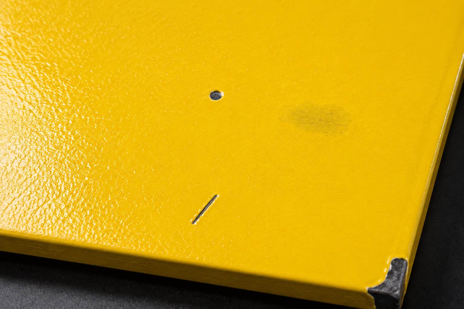
Some holidays are easy to see: bare corners, missed welds, scratches, chipped edges, open pinholes, cracks, and uncoated areas around bolts or supports. Others are too small to see under ordinary light. A pore may travel through the coating even though its surface opening is nearly invisible. A thin spot may appear covered but provide inadequate barrier protection or trigger an electrical detector.
The words holiday and discontinuity are often used together, but project specifications may define them precisely. In electrical testing, the important feature is a conductive path through a normally nonconductive coating to a conductive substrate. Visual inspection remains necessary because some coverage, thickness, or workmanship defects may not produce an electrical indication.
How the Breaks Develop
Application Coverage
- Spray angle, gun distance, pattern overlap, travel speed, poor lighting, or blocked access leaves an area uncoated or thin.
- Edges, welds, pits, threads, fasteners, backsides, corners, and complex geometry receive less film than broad surfaces.
- Excessive atomizing air, dry spray, poor wetting, high viscosity, or inadequate flow prevents the film from closing.
- Insufficient stripe coating or missed repair areas create predictable weak points.
Film Formation
- Air, solvent, moisture, substrate gas, or reaction products escape through the film and leave pinholes or pores.
- Contamination causes fisheyes, craters, crawling, or local dewetting that reaches the substrate.
- Porous concrete, welds, castings, galvanized surfaces, and thermal-sprayed metal release trapped air.
- Incorrect mixing, thinning, induction, pot life, flash, cure, or temperature disrupts film continuity.
Damage and Movement
- Handling, erection, shipping, tools, scaffolding, welding, grinding, impact, or abrasion cuts through the cured film.
- Cracking, checking, flexing, vibration, thermal cycling, or substrate movement opens a previously continuous coating.
- Sharp edges and rough welds concentrate film stress and are easily damaged.
- Premature service or inspection before full cure marks or punctures a soft film.
Inspection and Process Gaps
- The wrong detector method or voltage is used for the coating thickness and specification.
- Testing is performed before adequate cure, on a wet or contaminated surface, or without a reliable ground.
- Coverage speed is too fast or the probe does not contact the entire test area.
- Repairs are not retested, allowing the original holiday or a new repair-edge defect to remain.
Read the Pattern Before Repairing It
| Observation | Likely Direction | What to Check |
|---|---|---|
| Indications cluster at sharp edges, welds, bolts, seams, or difficult geometry | Low local film build, poor access, inadequate stripe coat, rough profile, or edge damage | Detailing, edge radius, weld condition, application angle, stripe-coat records, and DFT distribution |
| Many tiny indications spread across a broad area | Porosity, outgassing, pinholing, contamination, atomization, or incorrect detector setup | Surface porosity, environmental history, mix, thinner, spray settings, film thickness, cure, ground, and test voltage |
| Long narrow indication follows a scratch, crack, or handling path | Mechanical damage or coating movement after application | Handling sequence, access equipment, fabrication, transport, cure at time of damage, and crack depth |
| Indications follow one applicator pass or panel band | Pattern overlap, travel speed, gun adjustment, material delivery, or missed coverage | Spray pattern, pressure, tip condition, operator path, lighting, WFT records, and adjacent passes |
| Detector signals in damp, salty, dirty, or incompletely cured areas | Surface conductivity, moisture, contamination, or unsuitable test timing may be affecting results | Cleaning, dryness, cure, conductive components, specification, equipment instructions, and repeatability |
| A repaired holiday signals again at its edge | Incomplete removal, contamination, entrapped air, insufficient overlap, incompatible repair, or new damage | Repair preparation, feathering, overlap, material, cure, thickness, and complete retest |
Holidays Versus Related Defects
- Pinholes: tiny openings may or may not extend through the complete system. A through-film pinhole is a holiday; a shallow surface pore is not necessarily one.
- Porosity: describes voids within or through a film. Electrical testing detects only those that create a conductive path under the test conditions.
- Cratering and fisheyes: depressions caused by wetting problems are holidays only when they expose or connect to the substrate.
- Thin film: may fail the thickness specification without being electrically discontinuous. Conversely, a coating can meet average DFT and still contain holidays.
- Cracking: a surface crack is not necessarily through-film. Once it reaches the substrate, it becomes a discontinuity in the barrier.
- Peeling or delamination: loss of adhesion can exist beneath apparently continuous film. Holiday testing is not a substitute for adhesion assessment.
- Surface contamination: moisture, salts, conductive dust, or residue can create misleading indications or tracking; prepare the surface as the governing method requires.
Low-Voltage and High-Voltage Detection
Low-voltage wet-sponge testing uses a moistened sponge electrode to complete a circuit through a discontinuity to the conductive substrate. It is commonly associated with relatively thin, nonconductive coatings when allowed by the governing standard and specification. The wetting solution, sponge condition, travel rate, ground, surface cleanliness, and test timing must be controlled.
High-voltage testing uses a voltage sufficient to bridge the air gap at a discontinuity in a thicker nonconductive coating. The correct voltage depends on the written procedure, coating thickness, system, substrate, applicable standard, and instrument manufacturer. Excessive voltage can puncture or damage a sound film; insufficient voltage can miss defects. Never select voltage by guesswork.
A Practical Inspection Procedure
- Read the governing documents. Confirm the specified standard, detector type, voltage or solution, coating-thickness range, cure requirement, acceptance criteria, repair procedure, and retest requirements.
- Verify suitability. Confirm the coating is nonconductive, the substrate is conductive and accessible for grounding, and the system is compatible with the selected method. Conductive pigments or reinforcement can affect testing.
- Complete visual and thickness inspection first. Locate visible misses, damage, contamination, thin areas, runs, roughness, and incomplete cure. Holiday testing does not replace these inspections.
- Confirm cure and surface condition. Test only at the stage required by the specification. The surface should be sufficiently cured, clean, and dry unless the approved low-voltage method requires controlled wetting.
- Inspect and verify the instrument. Check calibration or verification status, battery, leads, electrodes, sponge, ground, audible and visual alarms, and operation according to current instructions.
- Establish a reliable ground. Connect to clean conductive substrate and confirm circuit continuity using the approved verification method.
- Set the required test conditions. Use the specified voltage and electrode, based on actual coating thickness and the governing procedure. Record settings and instrument identification.
- Scan systematically. Maintain full electrode contact and the prescribed travel rate. Cover flats, edges, welds, corners, penetrations, repairs, and difficult geometry without skipping bands.
- Mark without contaminating. Identify each confirmed location using an approved removable marker or mapping method that will not interfere with repair adhesion.
- Investigate the pattern. Confirm repeatability and distinguish true through-film defects from moisture, contamination, conductive material, poor ground, or equipment problems.
- Repair and retest. Prepare, coat, cure, and inspect each repair under the written procedure. Retest the repaired location and required surrounding area.
Standards and Their Scope
- ASTM D5162-21 — Discontinuity (Holiday) Testing of Nonconductive Protective Coating on Metallic Substrates.
- ASTM G62-23 — Holiday Detection of Coatings Used to Protect Pipelines.
- AMPP SP0188 — Discontinuity (Holiday) Testing of New Protective Coatings on Conductive Substrates.
These documents do not make every detector or procedure interchangeable. Follow the standard and edition named in the contract, along with the coating manufacturer’s limitations and the instrument instructions. Record any deviation and obtain written authorization before changing the approved method.
Correcting Holidays and Discontinuities
Do not simply dab material over an alarm location. First expose the complete extent of the defect and identify whether it is a missed area, pore, crack, contamination site, weak coating, mechanical puncture, or substrate problem. Remove unsound or contaminated material to a firmly attached boundary and prepare the substrate and adjacent coating by the approved method.
Apply the designated repair material at the required thickness and overlap, paying particular attention to edges and trapped air. Respect mix ratio, induction, pot life, environmental limits, recoat window, and cure. A repair that is tested too soon may be damaged; one tested too late may delay service. After cure, complete visual, thickness, adhesion, or other inspections required by the specification and retest for continuity.
When defects are numerous or repeat in a process pattern, isolated touch-up may not be reliable. Investigate whether the entire area has porosity, insufficient film, contamination, poor cure, or incompatible material. Removal and replacement may be more economical and defensible than hundreds of individual repairs.
Preventing Holidays
- Design, grind, or prepare sharp edges, welds, pits, projections, and difficult details as specified.
- Use stripe coats on edges, welds, corners, fasteners, and inaccessible geometry where required.
- Provide adequate lighting and access so the applicator can see and reach the entire surface.
- Control spray pattern, overlap, gun angle, distance, travel speed, viscosity, pressure, and material flow.
- Monitor wet and dry film thickness by area rather than relying only on an overall average.
- Control substrate temperature, ambient temperature, humidity, dew point, airflow, flash, and cure.
- Use suitable procedures for porous substrates, castings, concrete, welds, and surfaces prone to outgassing.
- Protect coated work during handling, assembly, transport, access, welding, and adjacent trades.
- Perform continuity testing at the specified production stage, then repair and retest before service.
- Track defect locations and frequencies; recurring patterns can identify a shift, applicator, geometry, material, or process-control problem.
Application-Specific Clues
Tank and vessel linings: Welds, pits, attachments, floors, sumps, nozzles, and repairs deserve special attention. Confirm that the detector method is compatible with the lining thickness, reinforcement, cure, and service.
Pipelines: Coating damage may occur during handling, bending, lowering-in, field-joint work, or backfilling. Use the project procedure and the applicable pipeline standard for plant, field, and repair testing.
Concrete and secondary containment: Electrical testing requires a suitable conductive path beneath the nonconductive lining. Moisture content, embedded conductors, primer, substrate preparation, and system design can affect feasibility and interpretation.
Powder coating, OEM, rail, marine, and structural work: Faraday-cage areas, hooks, racks, edges, welds, masking boundaries, assembly damage, and thin recesses can interrupt continuity. Not every cosmetic powder defect exposes conductive substrate, so confirm the failure depth.
Technical References
- ASTM D5162-21: Holiday Testing of Nonconductive Protective Coatings on Metallic Substrates
- ASTM G62-23: Holiday Detection of Pipeline Coatings
- AMPP SP0188: Holiday Testing of New Protective Coatings on Conductive Substrates
- Elcometer: Low-Voltage Pinhole Detection Overview
© 2026 Azimuth Spray Systems, LLC. AirSprayTech.com — The Finishing Authority®. All rights reserved.