AirSprayTech.com Academy — Finish Defect Diagnostic Center
Tiny Holes, Big Problems: Diagnosing Coating Pinholes
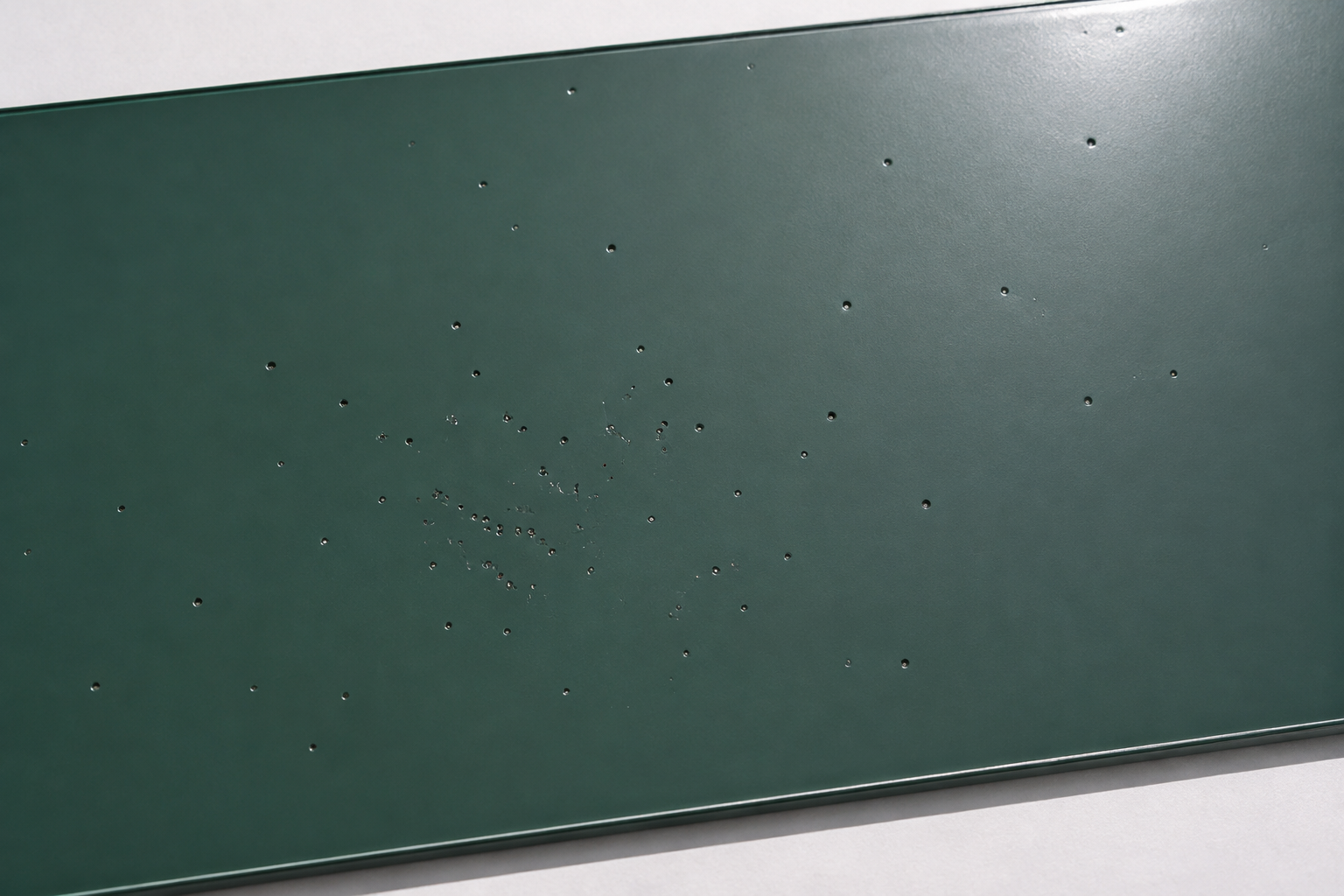
Pinholes are very small openings or pores in a coating film. Some stop within a single layer; others form a continuous path through the coating to an undercoat or substrate. They may be difficult to see without magnification or raking light, yet a through-film pinhole can compromise corrosion protection, chemical containment, water resistance, sanitation, electrical isolation, or appearance.
What Pinholes Look Like
- Tiny, round or irregular holes that resemble needle punctures.
- Individual pores or clusters concentrated over porous, filled, welded, blasted, or repaired areas.
- Openings that may reveal primer or substrate when viewed with magnification.
- A smooth surrounding film without the broad pulled-back rim typical of many fisheyes.
- Defects visible immediately after application, after flash or cure, or only during discontinuity testing.
- Early pinpoint corrosion or staining when a through-film defect has entered service.
The term “pinhole” is used differently across automotive refinish, architectural painting, powder coating, protective coatings, tank linings, pipelines, floors, roofs, composites, and OEM finishing. Always describe what was observed: approximate size, depth, density, location, coating layer, and whether the opening reaches a conductive substrate.
Common Cause Families
Porous Substrates
- Concrete, masonry, wood, fiberglass, composites, fillers, putties, and body repair materials.
- Cast metal, thermal-spray coatings, welds, seams, and rough galvanized surfaces.
- Air trapped in pores that expands after coating application.
- Surface profile too coarse for the applied film to bridge completely.
Air, Gas, and Moisture
- Entrained air from high-speed mixing, pumping, recirculation, or application.
- Outgassing as a porous or warming substrate releases air or vapor.
- Residual water, solvent, rinse solution, or moisture beneath the film.
- Gas produced during cure or released after the surface begins closing.
Material and Application
- Incorrect viscosity, reducer, mix ratio, induction time, or pot life.
- Poor atomization, excessive spray distance, dry spray, or inadequate flow.
- Film too thin to bridge surface profile—or too thick to release air and volatiles.
- Foam, aged material, moisture-sensitive components, or incompatible additives.
Powder and Cure Variables
- Porous castings, zinc surfaces, fillers, or heavily blasted substrates outgassing in the oven.
- Excessive film thickness or unsuitable object temperature.
- Damp powder, improper storage, aged or partially reacted material.
- Incompatible powders, contamination, cure by-products, or incorrect oven profile.
Pinholes Versus Similar Defects
| Condition | Typical Clue | Primary Investigation |
|---|---|---|
| Pinholes | Small, narrow pores that may stop within the film or pass through it. | Porosity, profile, entrained air, outgassing, film formation, thickness, and cure. |
| Fisheyes | Wet coating pulls away from a localized low-energy spot, usually leaving a broader circular depression and sometimes a center contaminant. | Oil, silicone, wax, cleaner residue, compressed air, and surface wetting. |
| Cratering | Bowl-shaped depressions of varied size and depth; the word describes shape rather than one cause. | Formation timing, wetting, gas release, material compatibility, powder process, and cure. |
| Solvent popping | Ruptured or volcano-like openings form when volatile material escapes after the film begins to set. | Film build, reducer, flash, airflow, part temperature, and bake schedule. |
| Holidays | Any discontinuity that interrupts coating continuity; this can include a through-film pinhole, miss, crack, or thin area. | Specified discontinuity method, detector type, voltage, coating thickness, substrate, cure, and acceptance criteria. |
| Dirt or inclusions | Raised particles or bumps rather than open pores. | Part cleaning, material filtration, clothing, booth, oven, conveyor, and airflow. |
A Practical Diagnostic Sequence
- Document before disturbing. Photograph the area under direct and raking light. Include a scale and record whether magnification was used.
- Map the distribution. Note whether pinholes follow filler, repairs, welds, castings, blasted areas, concrete pores, high points, horizontal surfaces, one gun, or one oven zone.
- Establish formation timing. Observe a test panel through application, flash, gel, cure, and cooling. Immediate pores and late-opening pores may have different mechanisms.
- Examine depth and layer. Use magnification or cross-sectional examination to determine whether the opening stops in the topcoat, reaches an intermediate coat, or extends to the substrate.
- Review the substrate. Record porosity, moisture, temperature, surface profile, filler or sealer, cleanliness, corrosion, and preparation history.
- Review the material. Confirm product, batch, storage, mix ratio, viscosity, reducer, induction, pot life, filtration, mixing speed, and additives.
- Review application. Check atomization, fluid delivery, powder output, gun distance, overlap, film thickness, wet edge, recoating, and stripe coating.
- Review cure conditions. Record flash time, airflow, humidity, substrate temperature, oven air temperature, actual part temperature, heating rate, and time at temperature.
- Use the specified discontinuity test. Where continuity is a requirement, test only after the coating has cured sufficiently and with the method, detector, voltage, electrode, and acceptance criteria stated by the governing specification.
Visual Inspection Versus Holiday Detection
Visual inspection can find surface openings, but it cannot always determine whether a pore reaches the substrate. Conversely, electrical discontinuity testing detects an electrical path through a nonconductive coating to a conductive substrate or underlayment; it does not necessarily identify every visible pore that stops within the film.
ASTM D5162-24 covers discontinuity testing of nonconductive protective coatings on metallic substrates. ASTM G62-23 addresses holiday detection of coatings used to protect pipelines. ASTM D4787-24 addresses continuity verification of liquid or sheet linings applied to concrete substrates.
Corrective Action
The repair must eliminate the pore and correct the process that created it. Simply wiping another coat over a pinholed surface may bridge the opening temporarily, trap air or contamination, or reproduce the defect.
- Cosmetic finishing: Follow the coating manufacturer’s repair procedure. Sand or remove affected material to the required sound layer, fill or seal substrate pores with approved materials, prime as required, and refinish.
- Protective coatings and linings: Mark every detected discontinuity, prepare each location by the specified method, apply the approved repair material to the required thickness, cure, and retest.
- Porous substrates: Correct moisture, outgassing, or trapped air. Approved methods may include preconditioning, preheating, sealing, skim coating, stripe coating, or applying at a more suitable substrate-temperature trend.
- Powder coatings: Address film thickness, part temperature, powder condition, compatibility, storage, outgassing, and oven profile before recoating or stripping and reprocessing.
- Exposed substrate: Remove corrosion and restore surface preparation and the complete coating system rather than covering rust or residue.
Prevention
- Inspect and repair pores in fillers, fiberglass, concrete, wood, castings, welds, and repairs before finish coating.
- Select primers, sealers, fillers, and coating systems approved for the substrate and service.
- Control surface profile so the specified coating can cover peaks and bridge valleys at the required thickness.
- Verify substrate moisture and temperature and avoid coating while porous materials are rapidly warming and releasing air unless the approved procedure permits it.
- Mix without unnecessary air entrainment and follow the specified induction, pot life, viscosity, filtration, and reduction.
- Apply within the product’s wet- and dry-film thickness limits; stripe-coat difficult areas when required.
- Allow the specified flash and recoat interval and verify actual part temperature during cure.
- Keep powder dry, segregated, within shelf life, and protected from incompatible material.
- Use representative test panels or production trials when the substrate, filler, coating, equipment, or cure schedule changes.
Application-Specific Considerations
Automotive refinish and composites: Pinholes often appear over body filler, stopper, fiberglass-reinforced plastic, or porous repairs. PPG’s defect guidance emphasizes careful inspection, correct mixing and application of filler, sealing of the substrate, and repair before the complete surface is refinished.
Powder coating: TIGER Coatings identifies possible contributors including excessive powder thickness, high object temperature, porous castings, coarse blast profile, outgassing, incompatible powder, aged or partially reacted powder, and excessive moisture. Trials should keep substrate, thickness, application, and cure controlled while changing one variable.
Concrete floors and linings: Concrete conductivity, moisture, porosity, conductive underlayments, coating cure, and service history affect continuity testing. ASTM D4787 is intended for the scope stated in that practice; previously exposed linings require special caution.
Roofs, wood, and masonry: Surface porosity, trapped moisture, and expanding air can create holes that resemble application defects. Diagnose the substrate and moisture path before adding material.
Documentation
Record the location, substrate, coating layer, approximate pinhole size and density, time of formation, surface profile, moisture and temperature, product and batch, mixing, application settings, wet- and dry-film thickness, flash and cure, photographs, test method, detector identification, calibration or verification, voltage, electrode, results, repair, and retest.
Technical References
- PPG Automotive Refinish: Pinholing—Causes, Prevention, and Rectification
- TIGER Coatings: Tips & Tricks for Powder Coating—Troubleshooting Guide
- ASTM D5162-24: Discontinuity Testing of Nonconductive Protective Coatings on Metallic Substrates
- ASTM G62-23: Holiday Detection of Coatings Used to Protect Pipelines
- ASTM D4787-24: Continuity Verification of Linings Applied to Concrete
- AMPP: Discontinuity Testing of New Protective Coatings on Conductive Substrates
Technical notice: This article provides general educational guidance. Always follow the current coating technical data sheet, safety data sheet, project specification, test-method edition, detector instructions, and applicable environmental and workplace requirements. Holiday testing can involve hazardous voltage and must be performed by trained personnel using the specified procedure.
© 2026 Azimuth Spray Systems, LLC. AirSprayTech.com — The Finishing Authority®. All rights reserved.